
· 2 min read

귀사의 업무 협조에 감사 드리며 무궁한 발전을 기원합니다.

표제의 건 관련, 부품공급 가능 기간 아래와 같이 안내 드리오니 업무에 참조 바랍니다.


기본적으로 단종 후 8년간 부품 공급 가능 및 이후 2년간 제한적인 부품 공급 및 AS 가능
단종 시점에서 연차 경과에 따라서 납기가 길어지고, 상황에 따라서 공급이 불가능한 경우도 발생할 수 있음.
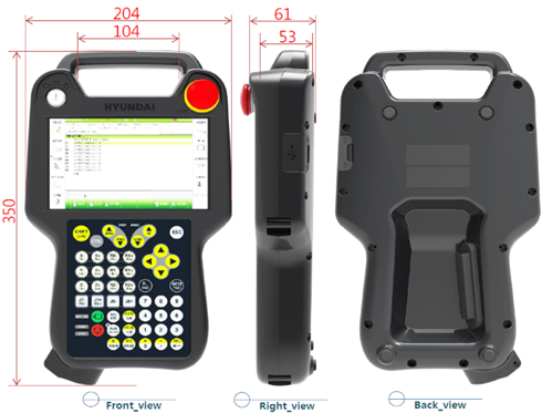
1. 제어기

모델명단종주요부품 공급가능기한
1Hi4, Hi4a2010년보유 재고에 한해 공급 가능, 별도 문의
2Hi52015년2025년까지
3Hi5a-N2021년2031년까지
4Hi5a-S2024년2034년까지

주요부품: PCB류, 서보엠프, TP
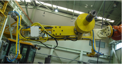
2. 본체

모델명단종주요부품 공급가능기한
1HR, HX (Hi4, Hi4a)2010년보유 재고에 한해 공급 가능, 별도 문의
2HX300, HX200L (Hi5)2015년2025년까지
3HA006, HA020, HA010L, HA006A, HA020W, HA010LW2015년2025년까지
4HS165, HS165S, HS200, HS150L, HS165D2016년2026년까지
5HS200S2019년2029년까지
6HH130L, HH100SL, YS140, HA006E2022년2032년까지
7HX400S2023년2033년까지
8HS260, HX5002024년2034년까지
9HA006B, HH012A, HH020, HH010L, HA006L, HH020L2025년2035년까지

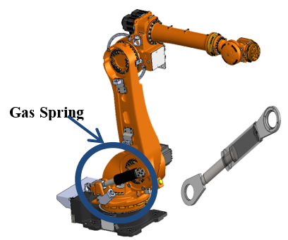
주요부품: 모터, 감속기, 외배케이블, WRIST ASSY, Balance Spring

· 2 min read

로봇 본체와 제어기 호기가 동일한지 확인

caution

외부 배선설치를 하기 전, 주전원을 차단한 상태에서 작업하시기 바랍니다.

외부 비상정지를 설치하여 사용할 경우에는 비상정지가 정상적으로 작동되는지 확인 후 로봇을 가동시켜야 합니다. 또한 비상정지 입력이 무효화가 되어 있는지 확인하십시오. 이는 작업자의 안전을 위하여 반드시 필요한 사전조치입니다.

제어기 외부 I/O, 안전 관련 배선 설치시에는 반드시 제어기의 전원을 차단한 상태에서 작업하시시 바랍니다.

제어기의 전원이 ON 상태에서 오결선으로 인한 단락 등이 발생시 회로보호를 위해 BD632보드의 Fuse(F3 또는 F5)가 끊어지게 되고 제어기 에러가 발생합니다.

이 경우 사용자 귀책으로 유상 A/S 대상입니다.

안전관련 입력을 연결하여 활성화를 한경우 반드시 “당사 제어기 보수 매뉴얼 1.11. 로봇 조작시 안전대책”을 참고하여 기능 정상 동작 여부를 확인하여 주십시오.

  • 비상정지의 연결
  • 안전가드의 연결
  • Safety PLC I/O의 연결 (안전입력, 비상정지 출력)
  • 외부 모터온 신호의 연결

· 3 min read

① Master Channel 통신 종류

  • EtherNet/IP : E
  • PROFINET IO : P
  • PROFIBUS-DP : B
  • CC-Link : C
  • DeviceNet : D
  • EtherCAT : T
  • 없음 : X

② Slave Channel 통신 종류

  • EtherNet/IP : E
  • PROFINET IO : P
  • PROFIBUS-DP : B
  • CC-Link : C
  • DeviceNet : D
  • EtherCAT : T
  • RAPIEnet : R
  • 없음 : X

③ <u>CC-Link IE사양일 경우에만 한자리 추가 (이외 추가 안함)</u>

  • CC-Link IE Master : M
  • CC-Link IE Slave : S

④ PCB Version

⑤ 년/월

⑥ Lot No.

⑦ 식별 코드 (필요 시 부가)

상기 ①, ② 작성 관련하여, 실물 구성이 Master만 2개 장착이라면, Slave 자리(②)에 숫자 2작성,

실물 구성이 Slave만 2ro 장착이라면, Master 자리(①)에 숫자 2작성 (CC-Link IE는 전용자리(③)가 있으므로 제외)

예시

  • 시리얼 라벨 : BD525EXS13-1507-001
  • 바코더 라벨 : B525EXS13-1507001B

PROFINET IO Slave + Slave 경우

  • 시리얼 라벨 : BD5252P13-1507-001
  • 바코더 라벨 : B5252P13-1507001B

예시2

BD525PP   PROFINET IO Master&Slave
BD525BB   PROFIBUS-DP Master&Slave
BD525CC   CC-Link Master&Slave
BD525DD   DeviceNet Master&Slace
BD525EX   EtherNet/IP Master
BD525PX   PROFINET IO Master
BD525BX   PROFIBUS-DP Master
BD525CX   CC-Link Master
BD525DX   DeviceNet Master
BD525TX   EtherCAT Master
BD525XE   EtherNet/IP Slave
BD525XP   PROFINET IO Slave
BD525XB   PROFIBUS-DP Slave
BD525XC   CC-Link Slave
BD525XD   DeviceNet Slave
BD525XT   EtherCAT Slave
BD525EXS  EtherNet/IP Master + CC-Link IE Slave
BD525XES  EtherNet/IP Slave + CC-Link IE Slave
BD525XXS    + CC-Link IE Slave

보드 사양

통신사양보드명(M/S, /S, M/)H/WS/W
PROFIBUS-DPBD525BB,BD525XB,BD525BXBD525+PROFIBUS 서브 모듈상이
디바이스넷BD525DD,BD525XD,BD525DXBD525+디바이스넷서브 모듈
CC-LinkBD525XCBD525+CC-Link서브 모듈
CC-LinkIE +EtherNetIP 마스터BD525EXSBD525+AB4788-B
EtherNetIPBD525EE,BD525XE,BD525EXBD525
PROFINET-IOBD525PP,BD525XP,BD525PX
EtherCATBD525TT,BD525XT,BD525TX

· 4 min read

1. Prior knowledge

  • You must prepare a USB memory containing the files required for version upgrade.
  • Deployment files must be named in a defined format.
   ex) Hi5aV402600.zip
    controller model(Hi5a) + V + major version(40) + minor version(26) + build revision(00)
  • All Hi5a controllers have a major version of "40" no see.
  • The minor version (26) is the actual significant version number.
  • The build revision is "00" for all official versions and all other versions are trial versions.
  • The Hi5a version is provided in ZIP format and is unpacked and installed by an automatic installer. (There is no need to intentionally unzip it.)

1.1. Precautions when downloading version

  • MV40 for TP530 users. If you download the version from 24 or higher to MV40.23 or lower, you cannot change the main version.
  • TP520/511 users are irrelevant.
  • After downloading the main version using TP520, you must reconnect and use TP530. At this time, when changing the version, only TP is performed.

2. Task sequence

2.1. Create a version upgrade folder with the name “Hi5a_rel” at the top path of the USB memory (based on TP511 \USB).

    \USB\Hi5a_rel

2.2. Copy the Hi5a controller S/W distribution file to the USB version upgrade folder.

    release file : for case : Hi5aV402600.zip
 EX) \USB\Hi5a_rel\Hi5aV402600.zip

2.3. Connect the USB where the distribution file is copied to the T/P.

2.4. Confirm that the T/P screen is switched as shown below.

2.5. Press the Version-Up button.

caution

  • Work with motor_off
  • Working in manual mode

2.6. After confirming that the screen changes as shown below, select the distribution file copied to the USB.

2.7. Confirm that the distribution file is selected and press the “OK” button.

2.8. The process of installing the distribution file on the T/P proceeds automatically. (Do not remove the attached USB while the above process is in progress)

2.9. Select the version compressed file that integrates the version upgrade files for each device.

Select the 2.10 version compressed file and press the ‘Start version upgrade’ button.

2.11 Automatically switches to a screen where you can check system information.

2.12 Compare version information for each device.

2.13 Click the checkbox of the device for which you want to upgrade to version 2.13 and change it to the checked state.

(You can upgrade only the parts you want.)

2.14 After final confirmation, press the ‘Confirm’ button.

2.15. The version upgrade for the selected device (single or multiple devices) is automatically performed.

3. An error occurred during installation

3.1. Distribution file installation failed

3.1.1. Cause

  • If the USB is arbitrarily removed from the T/P during installation of distribution files
  • When the distribution file itself is invalid (file is broken)

3.1.2. Solution

  • Reinstall the USB and try upgrading again.
  • If the file is corrupted, it must be replaced with a normal distribution file. (Please re-request the distribution file.)

3.2. Decompression failed

3.2.1. Cause

  • Occurs when the temporary storage space inside the T/P is insufficient.
  • Occurs when the distribution file or version compressed file is broken.

3.2.2. Solution

  • If the cause is insufficient temporary storage space, restart the T/P device.
  • If the file is damaged, replace it with a normal distribution file and apply.

3.3. Communication error

3.3.1. Cause

  • Poor Ethernet cable connection between main board and T/P
  • Main S/W is unable to communicate

3.3.2. Solution

  • Check the Ethernet cable wiring condition and retry.
  • Restart the Hi5a controller. (OFF -> ON)

3.4. Controller status not received

3.4.1. Cause

  • Communication error
  • Main S/W malfunction

3.4.2. Solution

  • In case of communication error, check error measures.
  • In case of main S/W malfunction, ignore it and proceed. (Press OK button) In case of main S/W malfunction, 7-segment of Main B/D: E52, dbg.

· One min read

Problem

  • Since the S/W of TP520 and TP530 are different, problems arise when installing unsuitable S/W.

Precautions

  • TP520 and TP530 cases are the same.
  • JOB program and UI Compatible without change.
  • Differences in Win OS There may be differences in S/W. (see next)
  • TP530 S/W cannot be installed on TP520 H/W. (Same for vice versa)
    • EX) MV40.21 (for TP520) ≠ MV40.21 (for TP530)
  • Installing another OS may occasionally cause TP system errors.

Differences between TP520 and TP530

division

TP520

TP530

RAM

DDR2 256Mbyte

(400MHz)

DDR3 1Gbyte

(933MHz)

Memory

NAND Flash 1GByte

eMMC Flash 8GByte

OS

Window CE 6.0

(TP511 has the same S/W as TP520)

Window Embedded Compact

※ The appearance of TP520 and TP530 is the same.

· 2 min read

Understanding allowable torque and moment of inertia

  • The payload of the robot (Payload: model below - 165Kg) is sufficient for the robot to carry and work. It refers to the weight.
  • Even if the payload is 165Kg, the farther the center of gravity is from the reference point, the more torque there is. As it gets bigger, the allowable payload becomes smaller . (See picture below)
  • Based on the center of gravity Even if the torque value is the same, the moment of inertia varies depending on the speed. It gets bigger.
  • In other words, even if the tool or workpiece is light if the center of gravity is far from the reference point, The allowable payload decreases drastically.

- If the moment of inertia or torque exceeds, the distance from the possible reference point is determined. It is better to reduce it.

- The allowable payload of the robot is proportional to the tool weight and the square of the distance. It is inversely proportional.

Excess Use Cases

Applicable robot: HS165 (carrying weight 165Kg), tool (145Kg)

It seems that there will be no problem by installing a tool that is less than the payload, but the tool The distance between the center and the reference point appears far.

(Robot: HS165, tool weight: 145Kg)

Find the distance and inertia of the tool's center of mass.

  • Use robot load estimation software
  • Use of 3D modeling data from tools

The result of applying the load calculation is as follows.

  • Weight: Outside the range of use.
  • Torque: 4,5 axes not available
  • Inertia: Not available for 4th and 5th axes

How to improve when overload

  • If the load is exceeded, reduce the tool weight or **reduce the load to the center of gravity of the tool. There is a way** to reduce the distance.
  • A method of reducing the distance is more effective. There are two ways as follows: When improving by method , if only the weight is reduced, the excess inertia will not be improved. No.
  • Load calculation uses our load analysis program HRLoad. (HRLoad download)

When reducing weight

· One min read

EUREKA 114 was developed to solve the initial noise problem of  VIGO RE 0 . , VIGO This product has greatly improved initial test operation noise compared to grease. However, please be aware that mixing the above greases together in the same reducer may cause some noise.

1. Problem

  • VIGO + EUREKA Noise occurs when mixed oil
  • Noise persists when the ratio of VIGO or EUREKA is more than 20%

2. History

The grease for the reducer applied to our robots is as follows.

  • VIGO RE 0: Period of use 2014 ~ 2020.9 (based on HS165, HS220)
  • EUREKA 114: Period of use 2020.9 ~ (based on HS220)

3. There is no major problem if you inject it after removing the existing grease.

If you are working with mixed grease, please replace it using the method below.

  • Residual amount suggested by manufacturer: 10% (Noise usually disappears when less than 20%)
  • In order to maintain the remaining oil amount below 10% during actual grease replacement work, the push method must be performed more than 3 times.

Reference 1. grease can

VIGO RE0

EUREKA 114

Reference 2. grease filler sticker

· One min read

Gas spring monitoring

Hi5a controller provides the function to monitor the pressure of the gas spring to manage the gas spring type balance spring.

The prerequisites for using this feature are as follows:

  • Function provided only in controller main software MV40.17-00 or higher
  • The actual pressure of the gas spring must be accurate. (140bar) – monitoring for subsequent changes
  • Robot load estimation must be performed accurately.

See manual for details

Function comparison

info

Pressure estimated at rest is less accurate than pressure estimated using the command method. If an abnormal pressure is detected in a stopped state, re-estimate the pressure using the command method or measure the actual pressure using a pressure gauge. If the estimated pressure at rest is still significantly different from the estimated pressure by command method, set the 'Estimation gas pressure at rest' setting to 'Estimate' or 'Invalid'.

How to use

Error details

· 2 min read

Gas pressure testing and injection

Pressure check

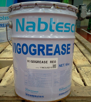
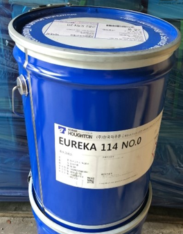
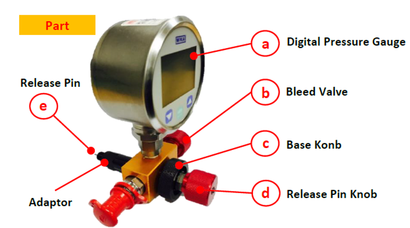
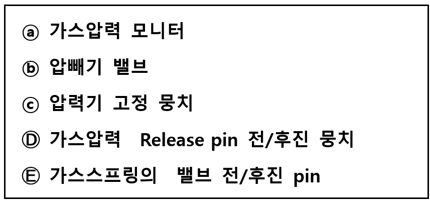
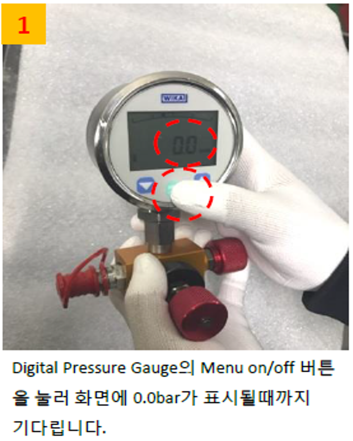
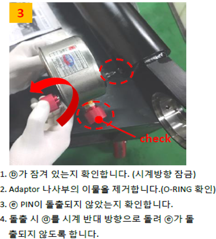
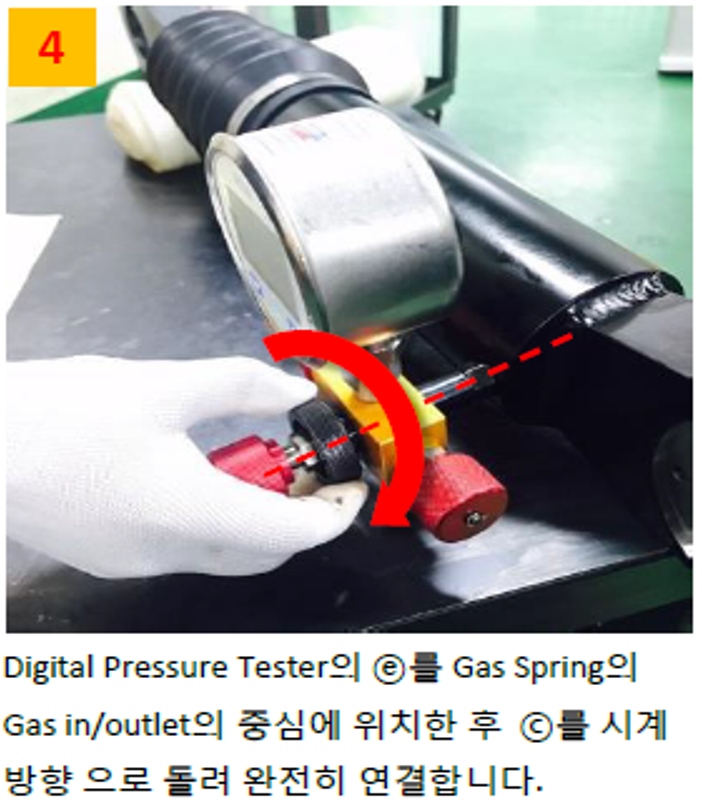
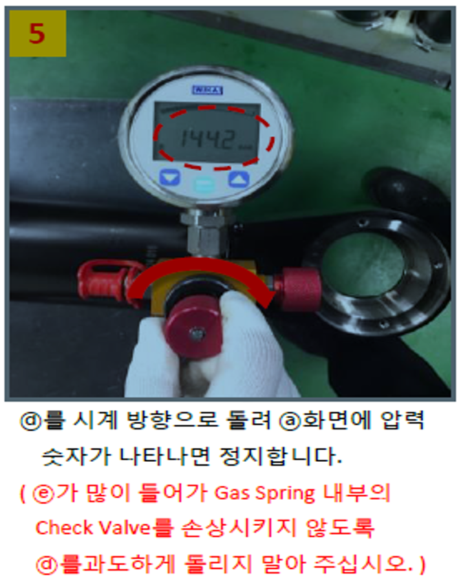
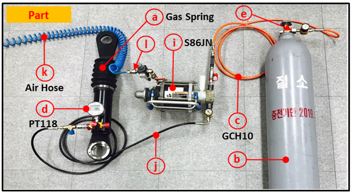
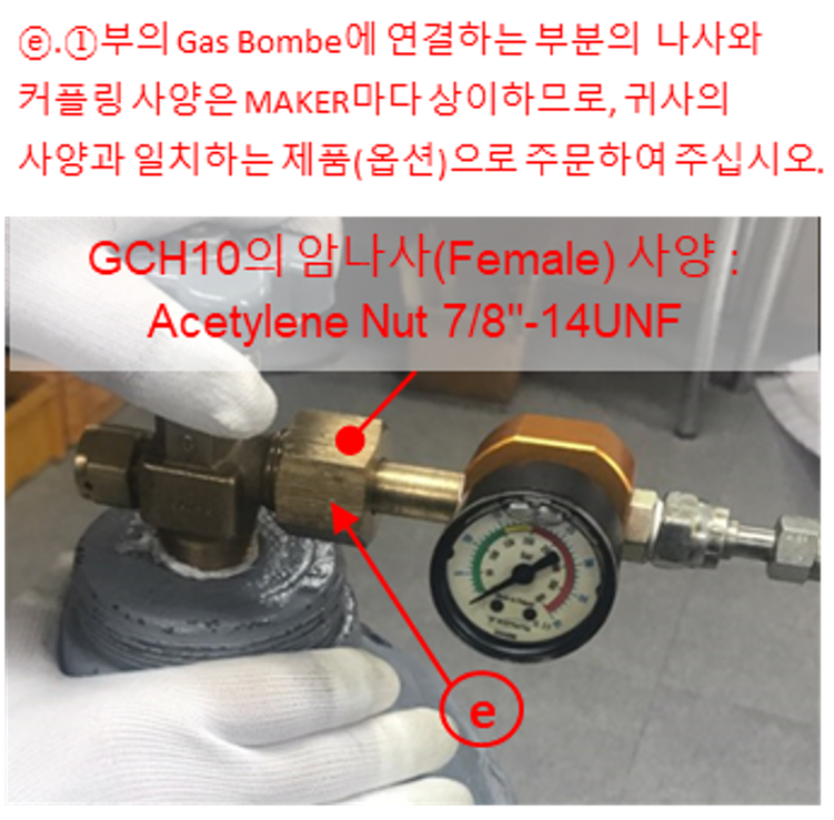
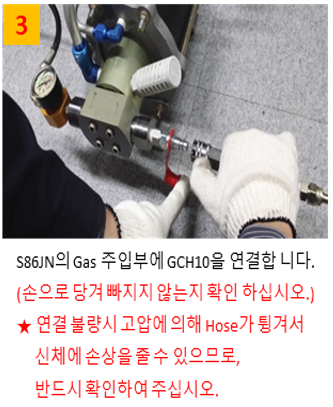
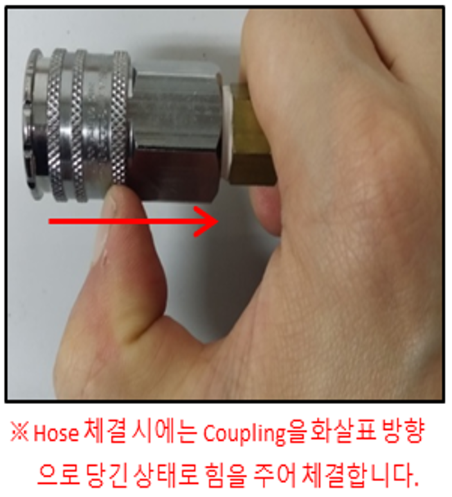
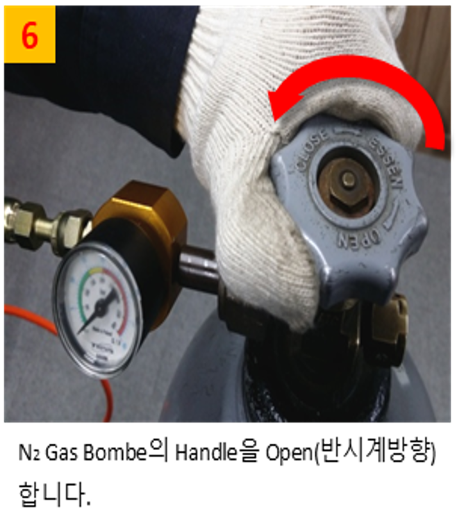
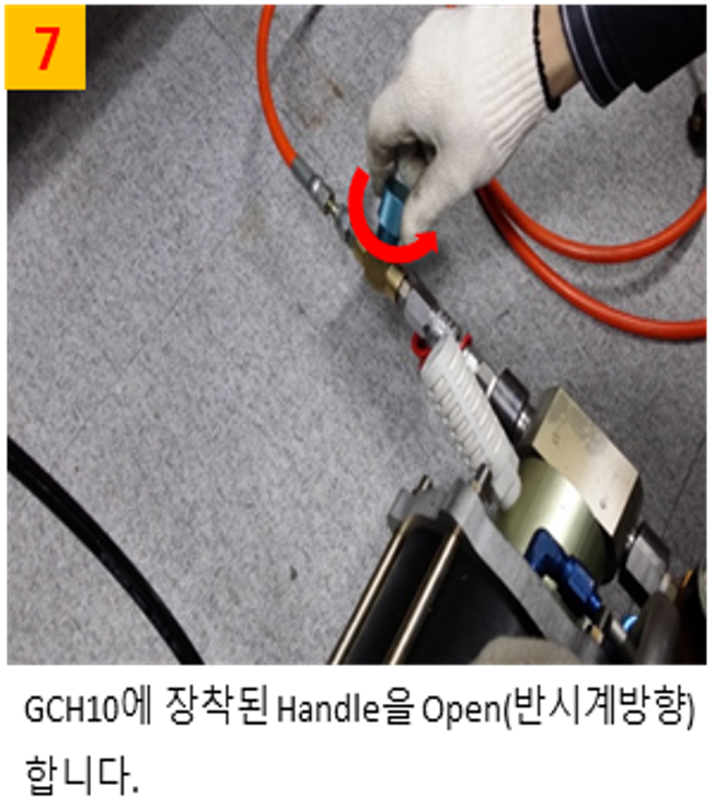
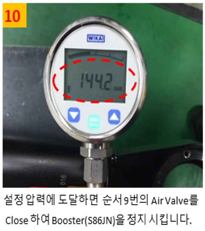
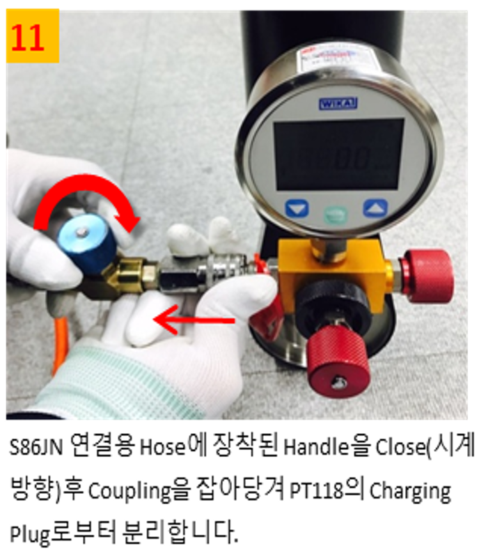
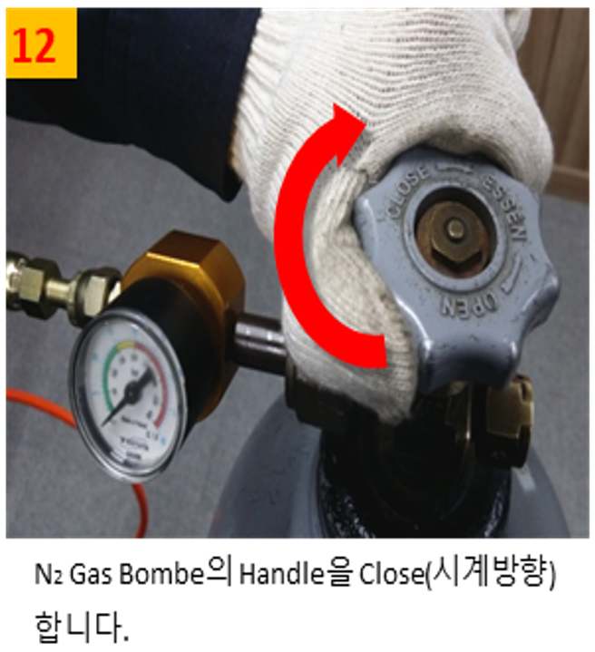
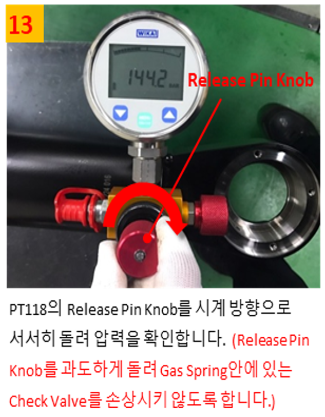
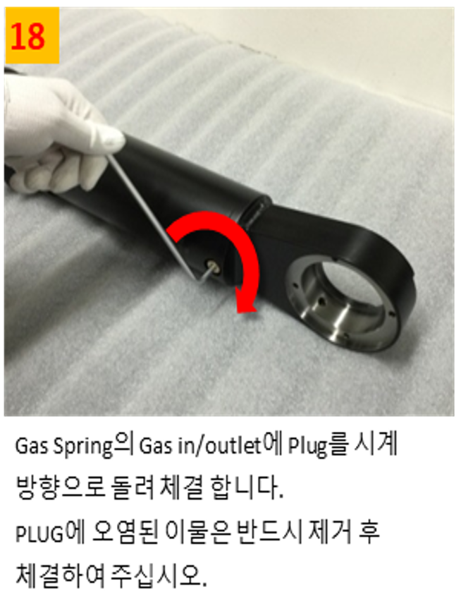
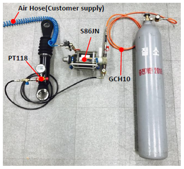
Gas spring filler SET 
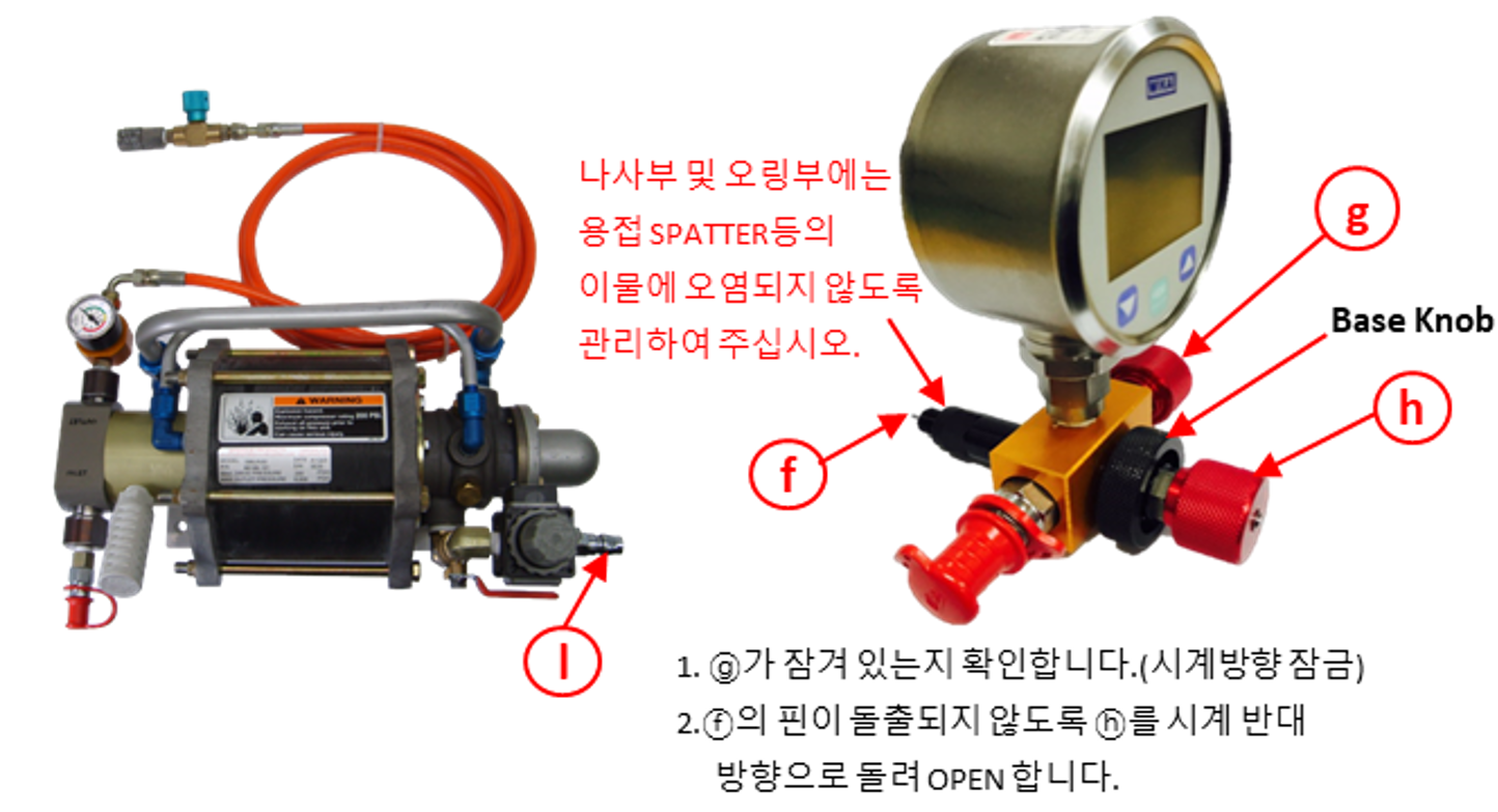
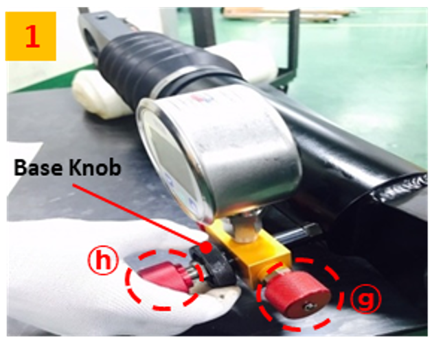
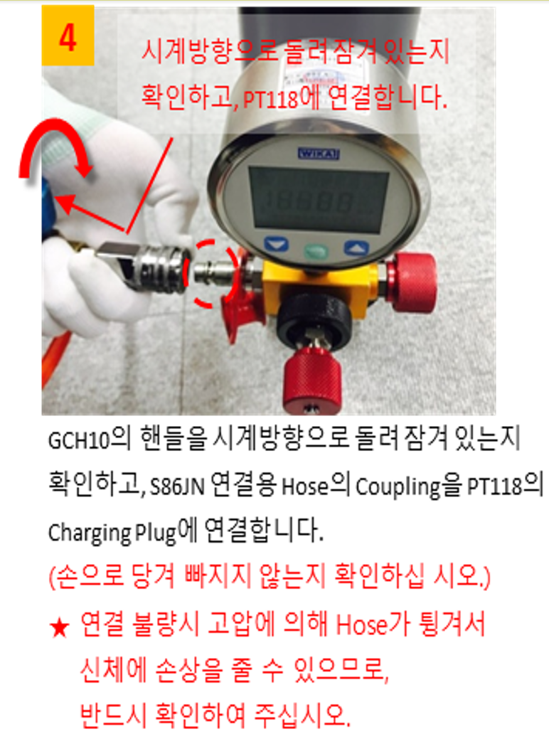
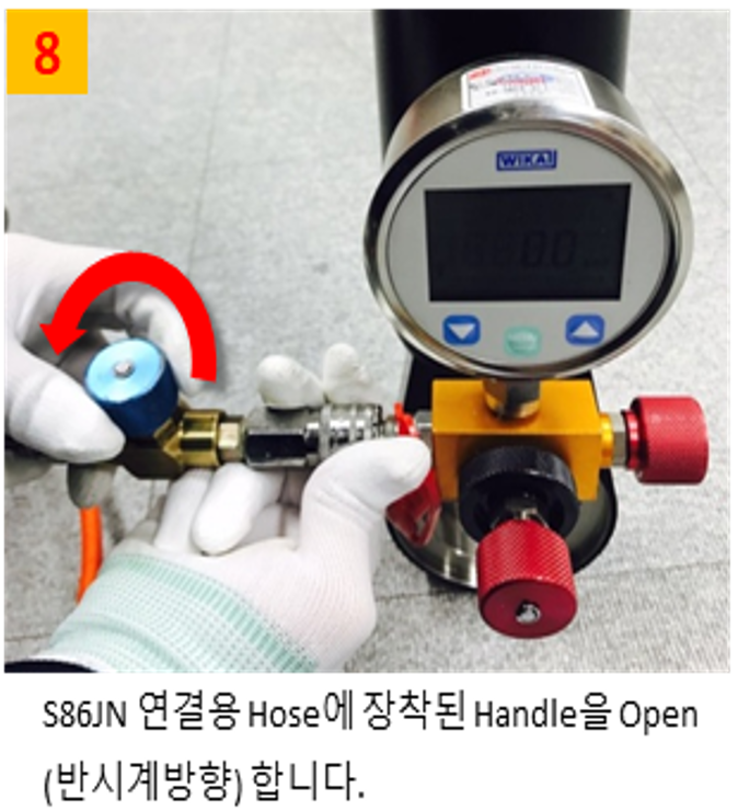
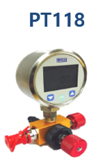
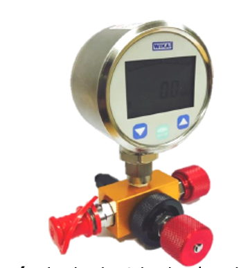
(digital pressure meter) 
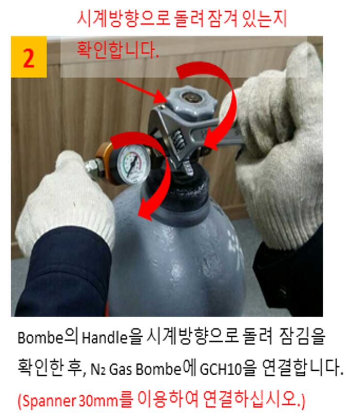
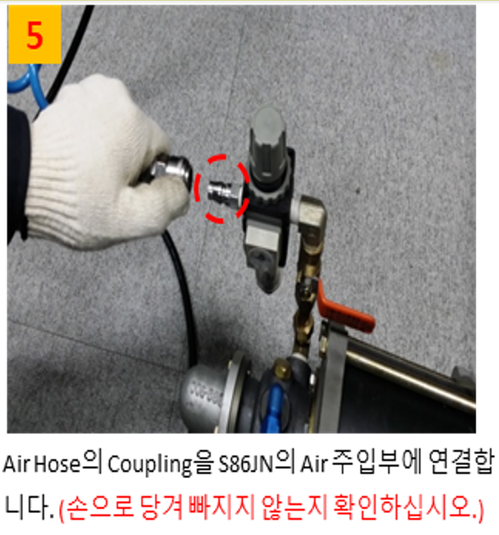
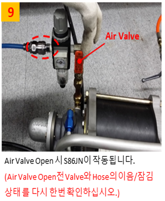
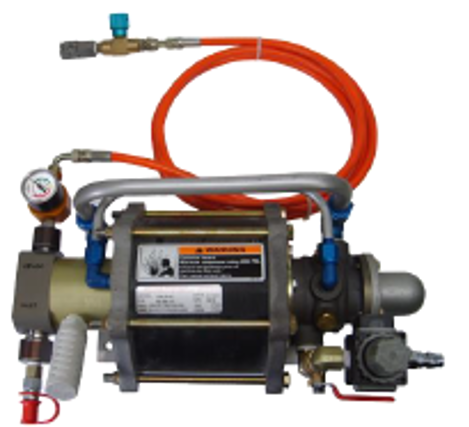
(pressure injection booster)

pressure check

gas injection

caution
  • Since nitrogen gas filling is high pressure, please follow the safety regulations of your country.
  • Nitrogen gas filling and inspection must be performed by trained personnel and in accordance with the manual.
  • Please fill only nitrogen gas. (Never fill gases other than nitrogen gas or liquid nitrogen.)
  • Be sure to wear safety glasses when working.
  • Never look directly into the gas inlet or pressure gauge.
  • If damage occurs, such as when assembling a gas spring with a different stroke, completely remove the gas and then separate it.
  • For safety considerations and to preserve product performance, disassembly and assembly of gas spring internal parts can only be done using designated standard work tools and equipment with appropriate training and understanding of the product. For inquiries regarding this, please contact us. Please contact us.
  • When measuring gas pressure, please follow the manual as incorrect operation/mistakes of the measuring device can cause a decrease in gas pressure.
  • Gas replenishment and filling must be performed with the gas spring assembled on the robot.
  • Set the robot's H-axis (2 axes) posture to the origin of 90° and turn off the power to the controller.

· 2 min read

Gas springs have the advantage of being lighter and requiring less replacement time than coil springs, but as they are devices that use high-pressure gas, natural leaks occur. Periodic inspection by the user is required to manage this.

Application ModelHS180/220, HH300,HS200L
Replacement M/H0.5 hours (depending on environment)
integrityPeriodic inspection. Twice a year (refer to manual)
caution
  • Problem that occurs when gas spring pressure drops: H-axis overload error occurs (robot stops)
    • Depends on the level of leakage. Depending on the load on the H axis, it may not occur even if the entire amount of leakage occurs.
    • Overcurrent warning occurs (H-axis warning needs to be checked)

How to check pressure

  • Apply pressure automatic detection function (Hi5a version MV40.17.00 or higher)

    • Warning occurs below 60 bar
    • Error occurs below 30 bar (robot stops)
    • Warning level can be manually set in T/P (details announced later)
  • Manual measurement using a pressure gauge (general pressure gauge: digital (PT118) recommended)

How to respond when pressure drops

pressure(bar)Action takemeaningnote
140~100maintainThere is no or minimal leakage.
100 or lessgas fillingPressure decrease due to natural leakageUse after filling
100 or lesssubstituteRapid deterioration due to seal damageFirst filling test required
  • Problems when using gas springs while neglecting natural pressure drop
    • The friction angle between the cartridge and the tube increases, causing damage to the seal.
    • Early damage to gas springs occurs