- 단종모델 부품 공급 기한 안내
- 그리스 혼유 금지 및 LB00 사용 권유 공지
- Hi6 USB 사용시 주의사항
- 원격속도조절기능 사용시 주의사항
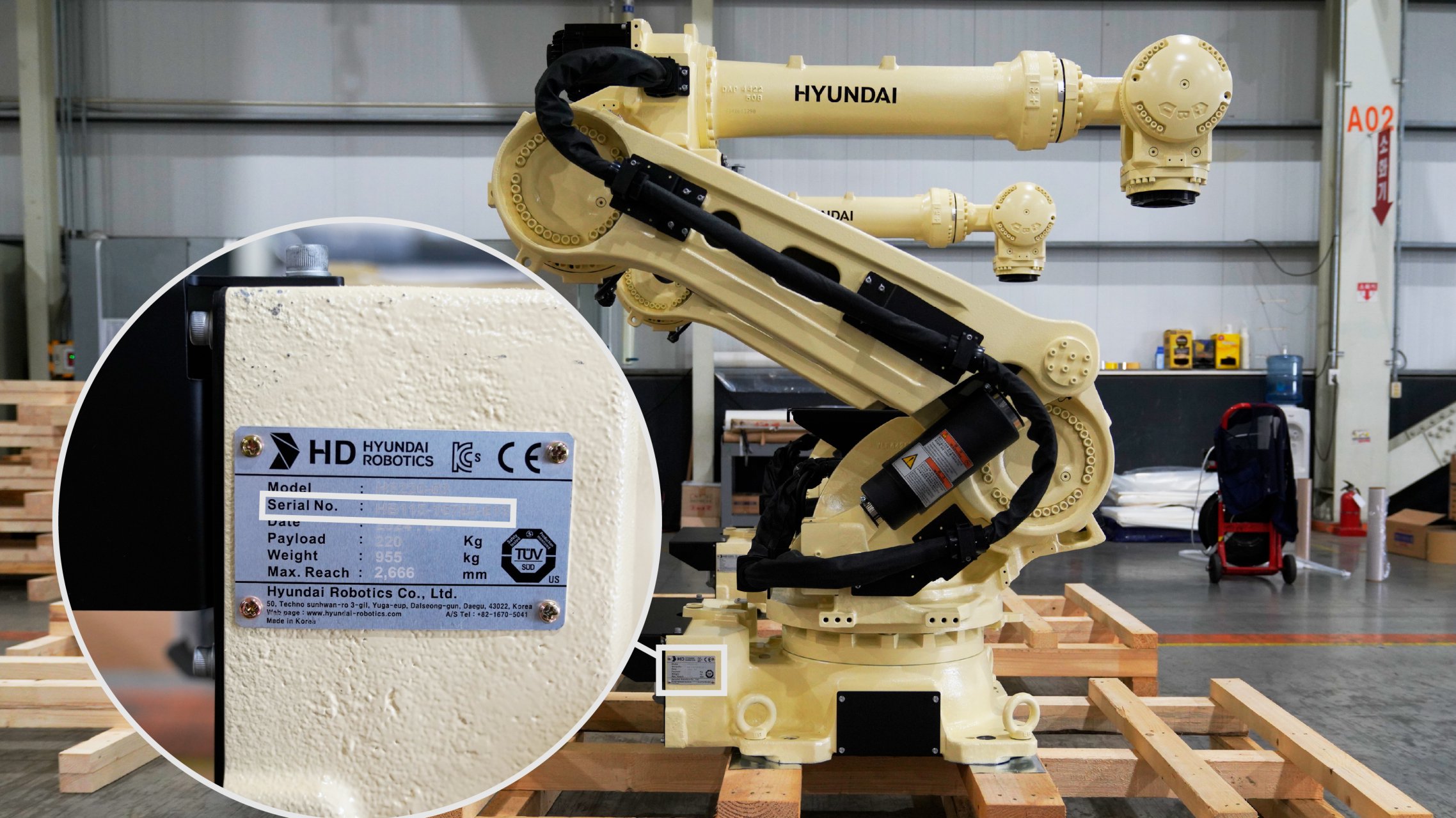
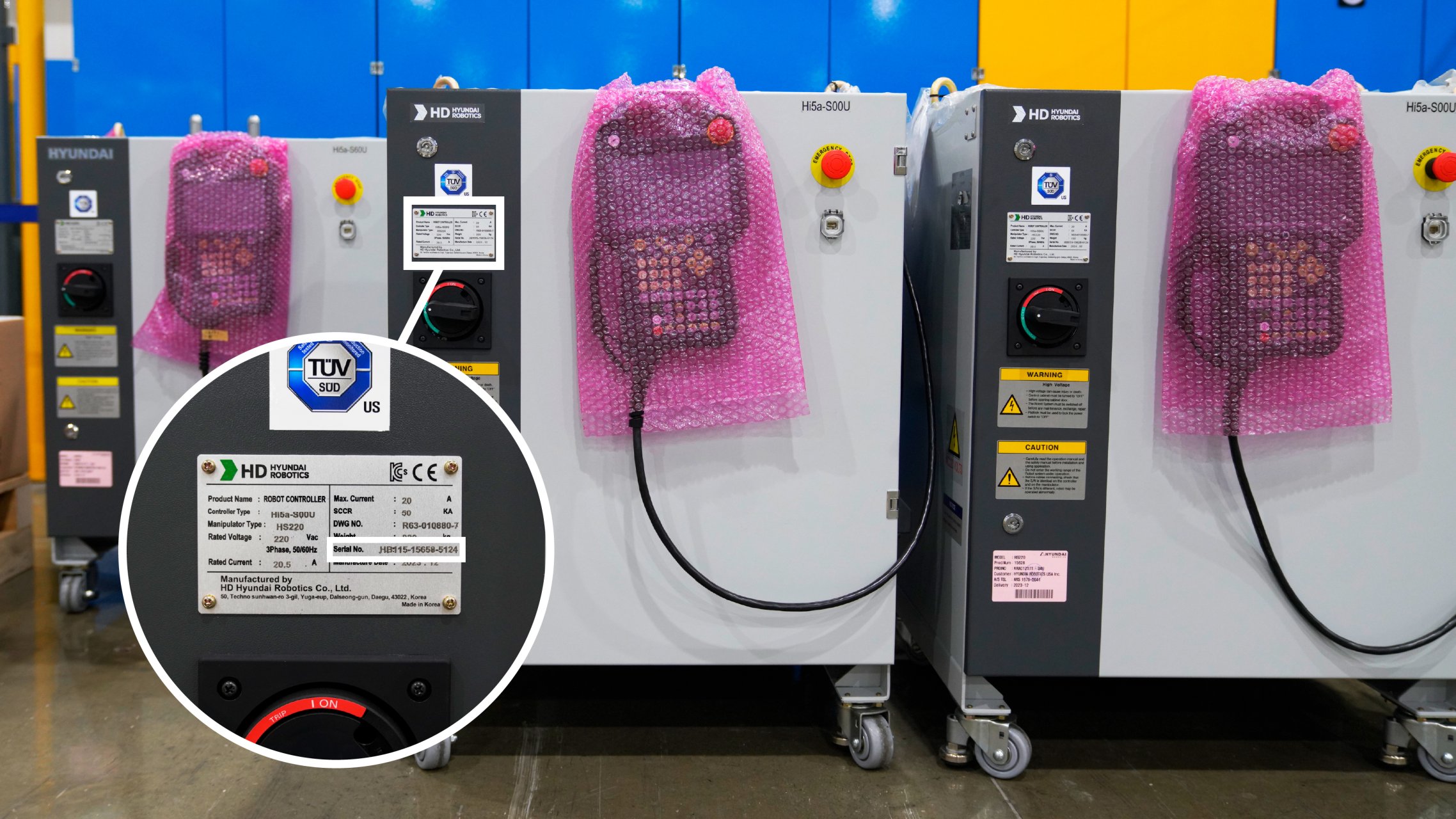
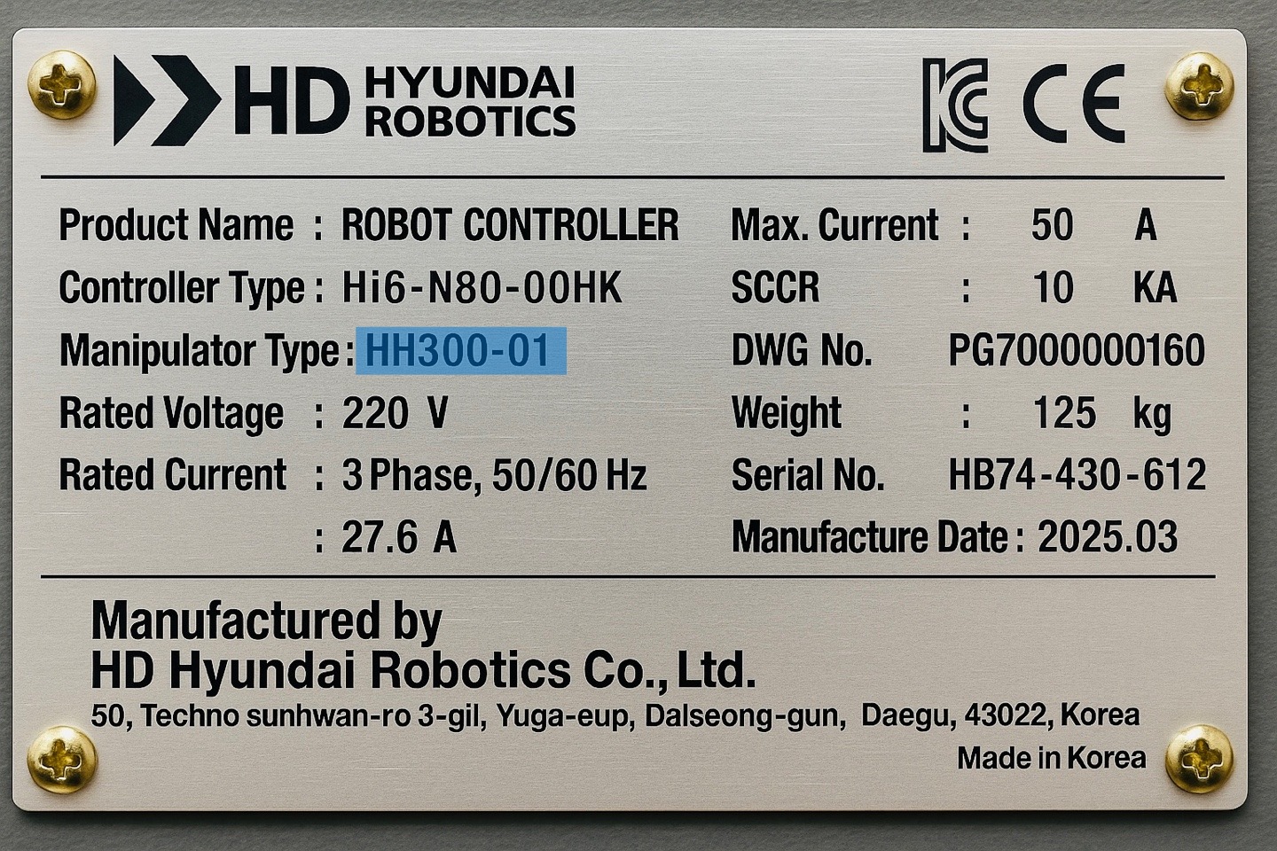
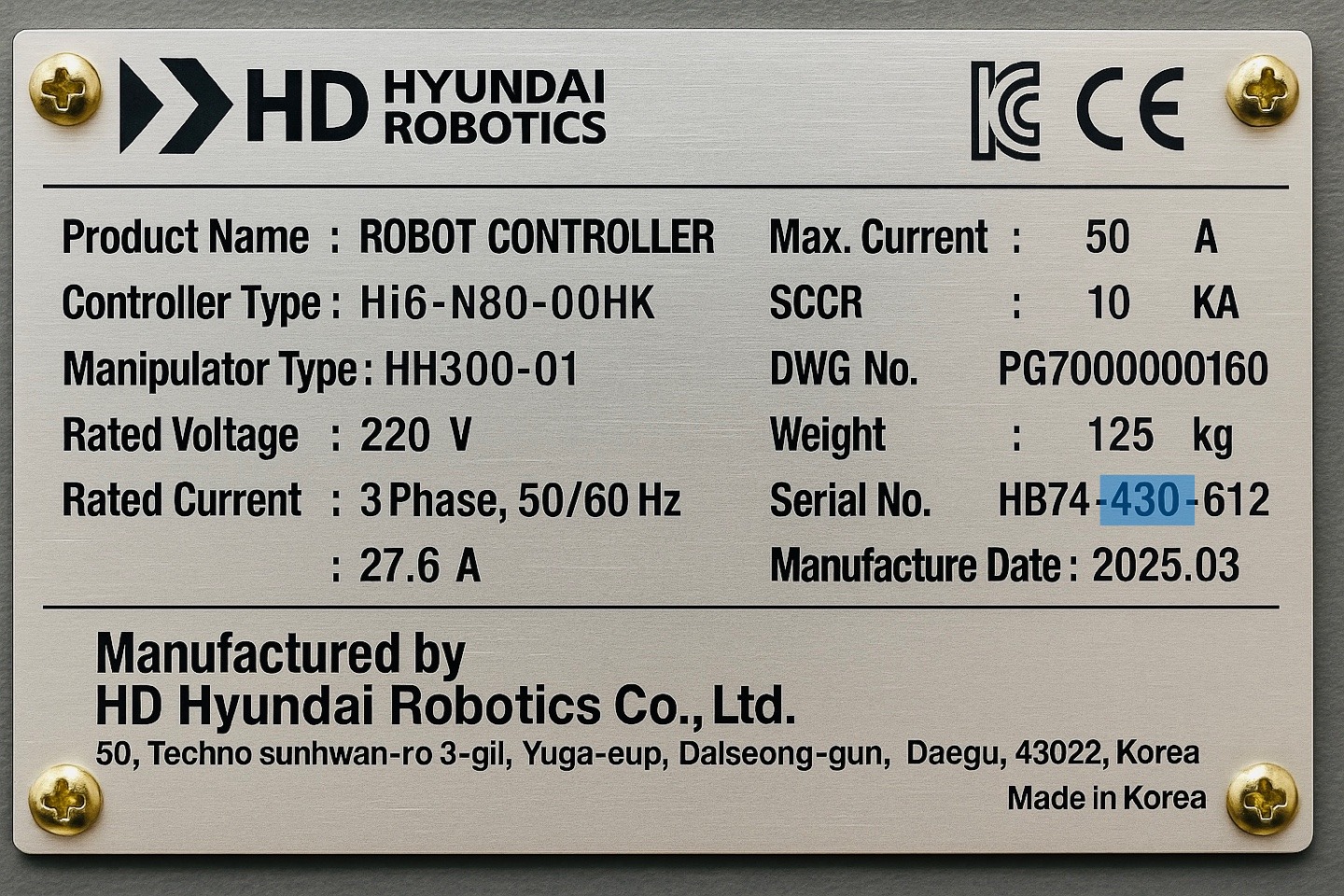
- AS접수시 로봇 호기 확인 방법 안내
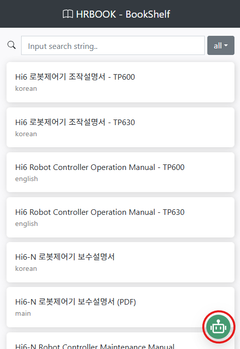
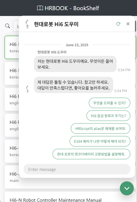
- Hi6 매뉴얼 챗봇 사용 안내
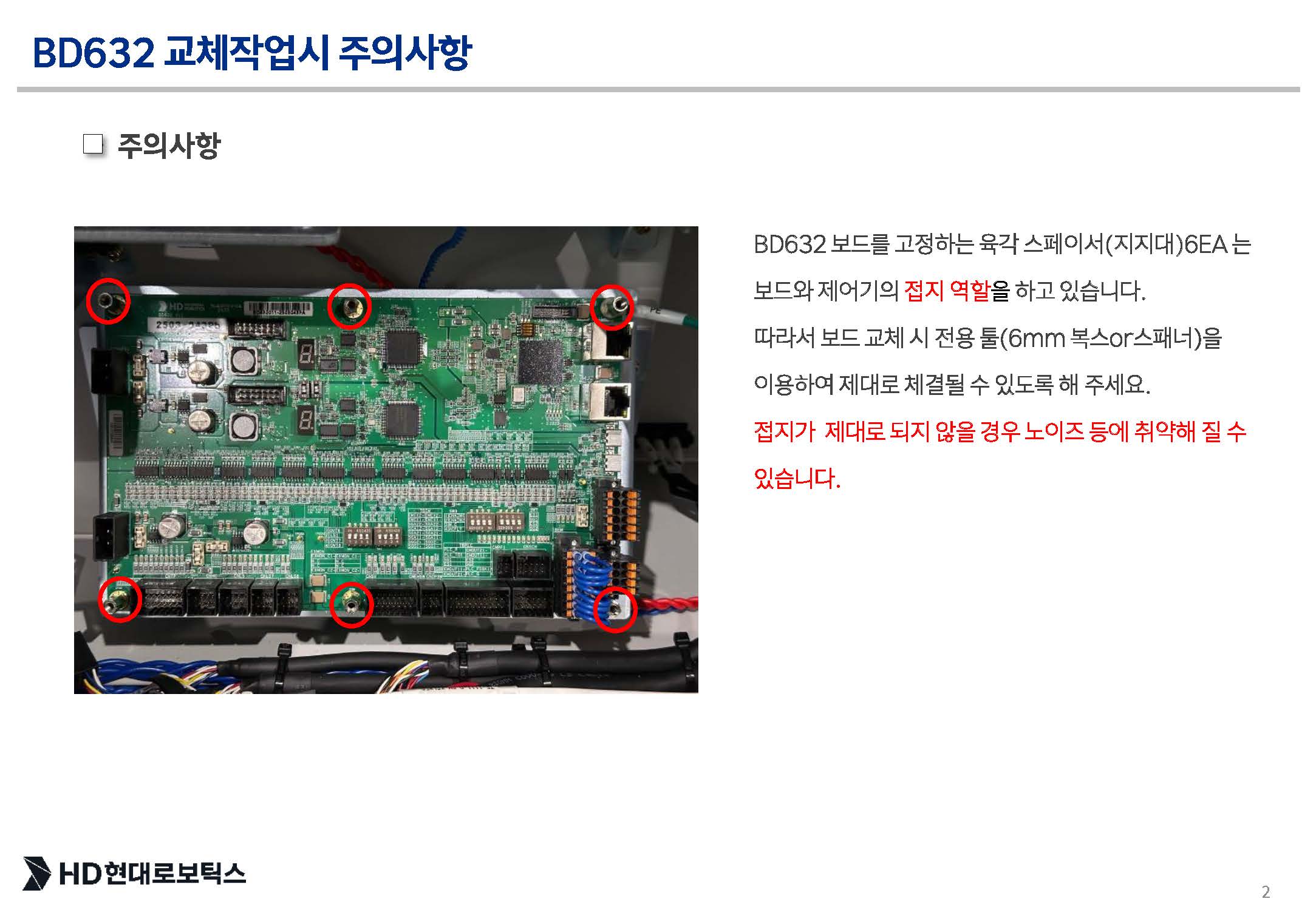
- Hi6 BD632 교체시 주의사항 안내
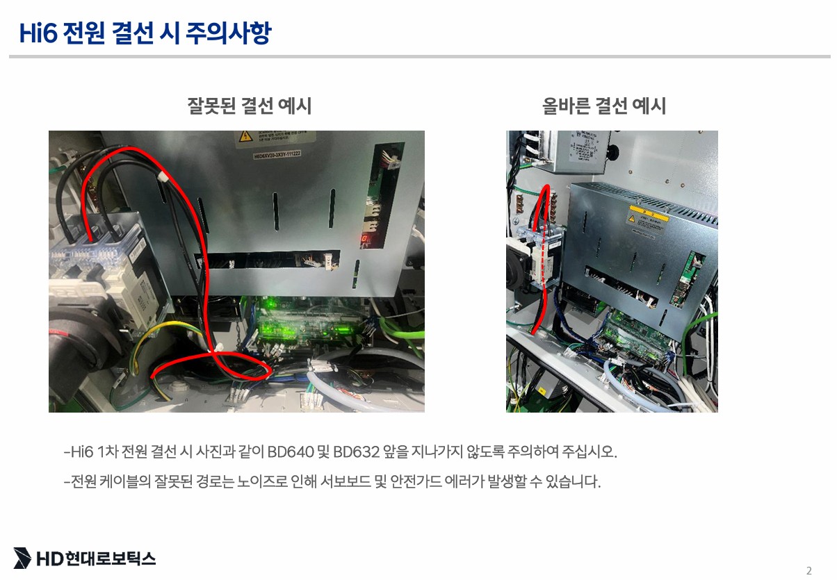
- Hi6 1차 전원 결선 시 주의사항 안내
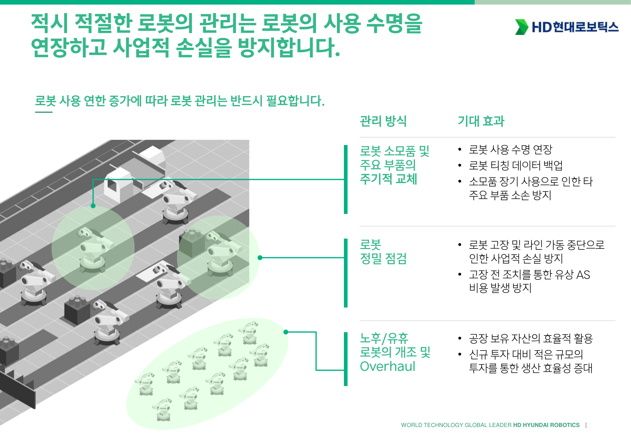
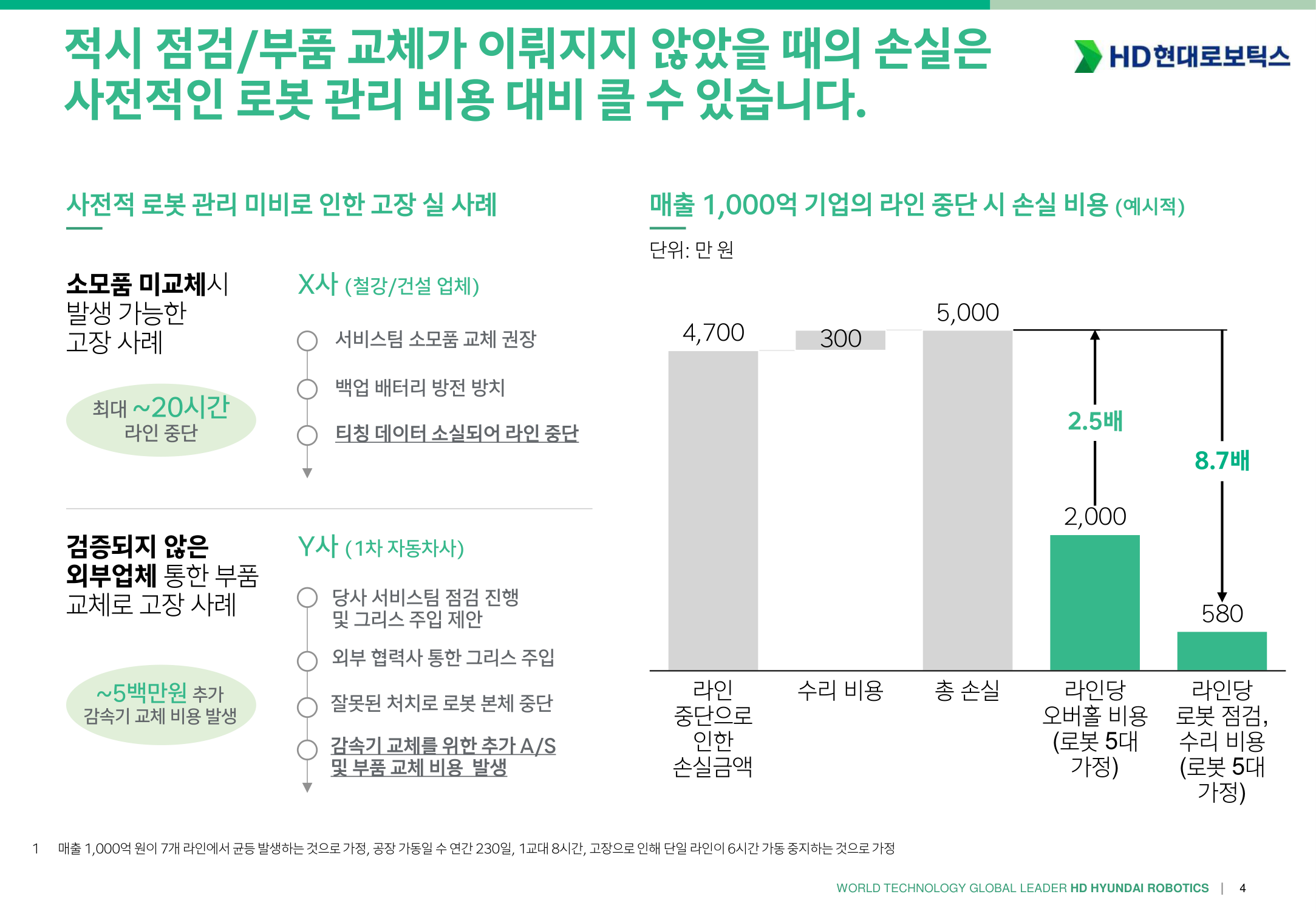
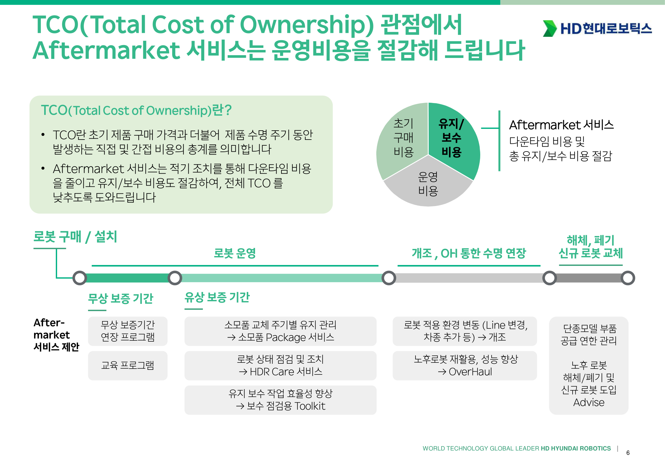
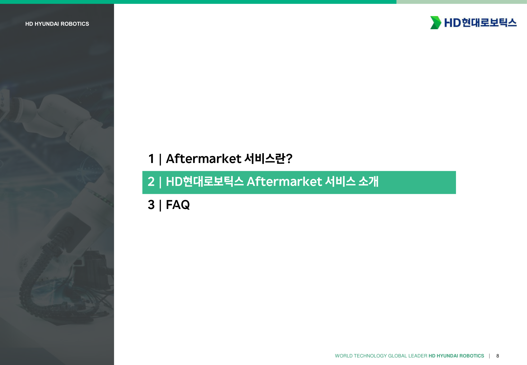
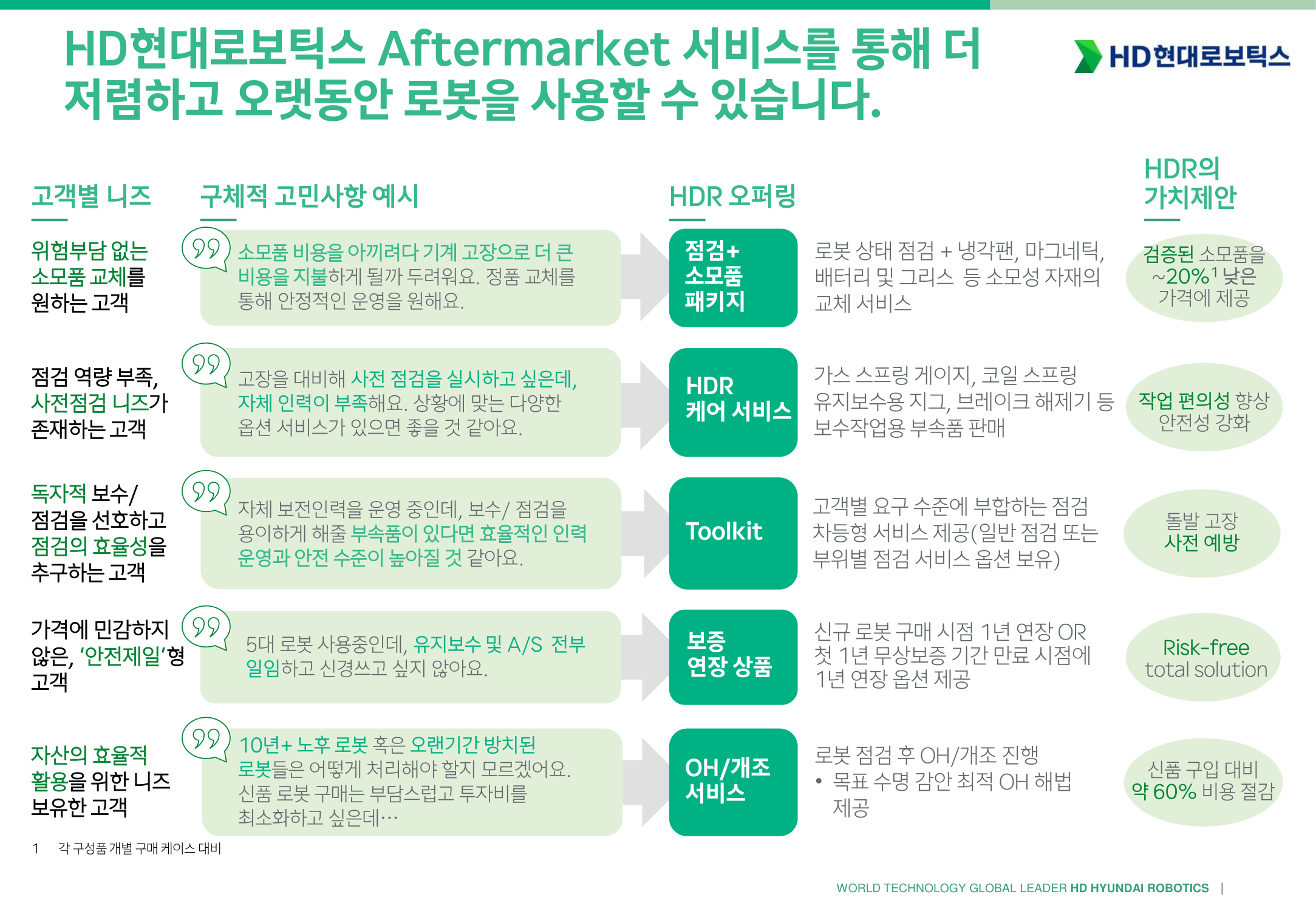
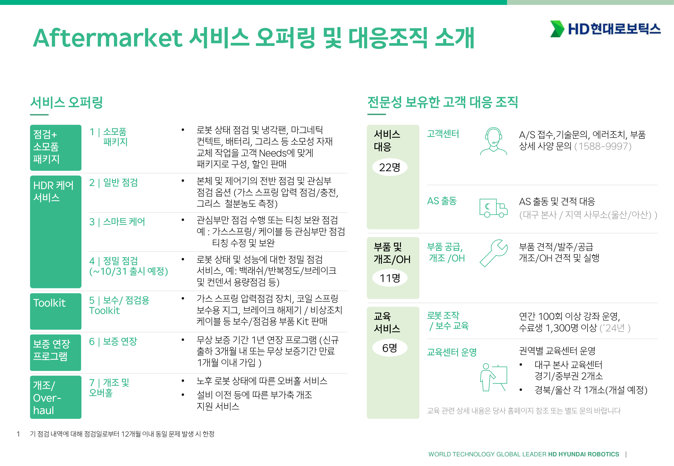
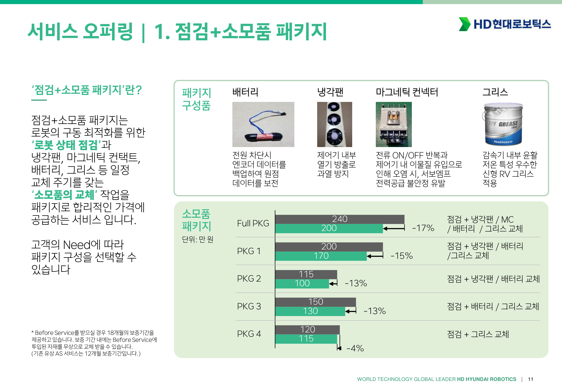
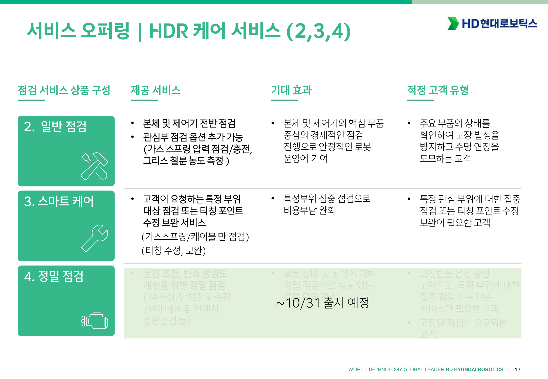
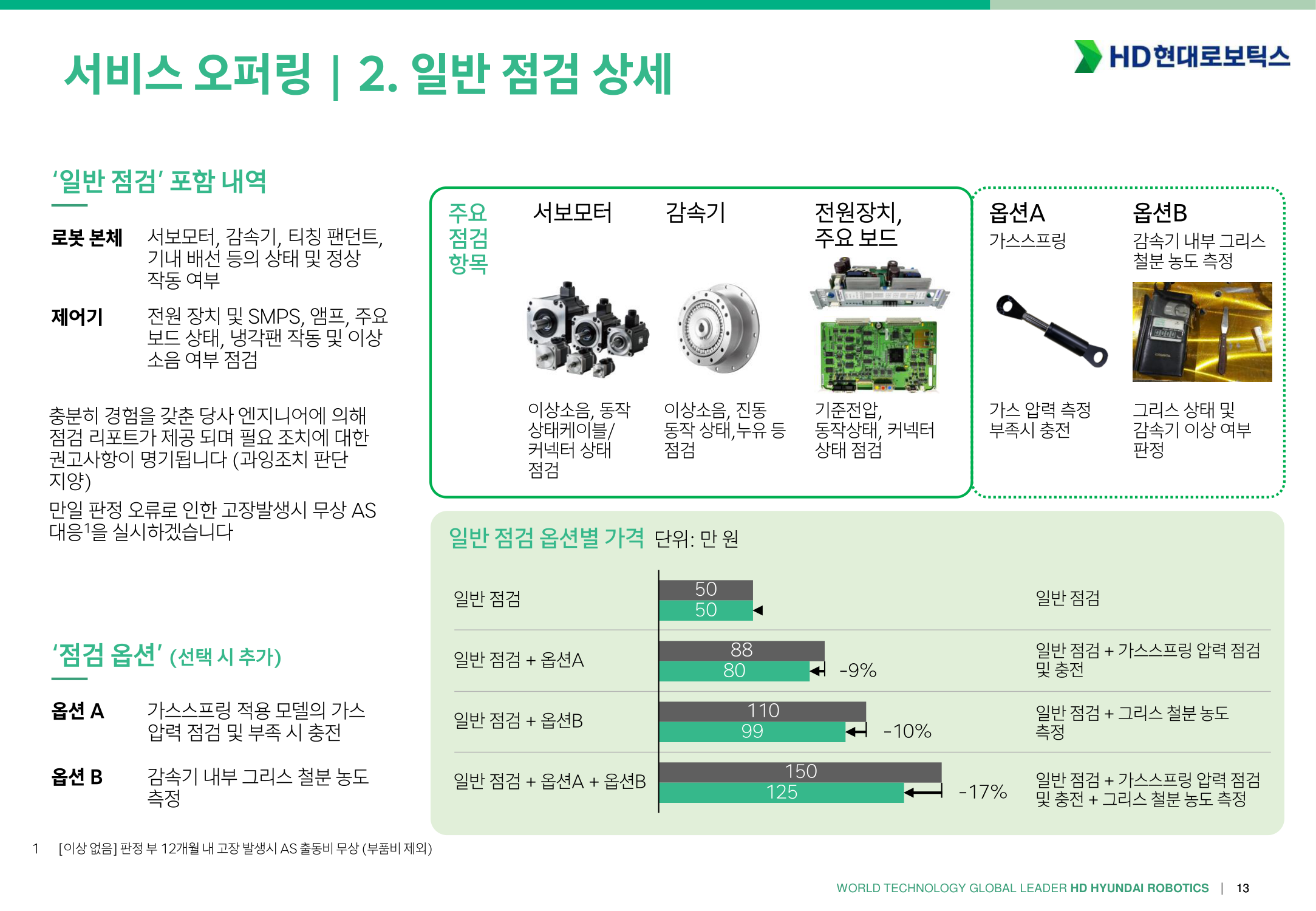
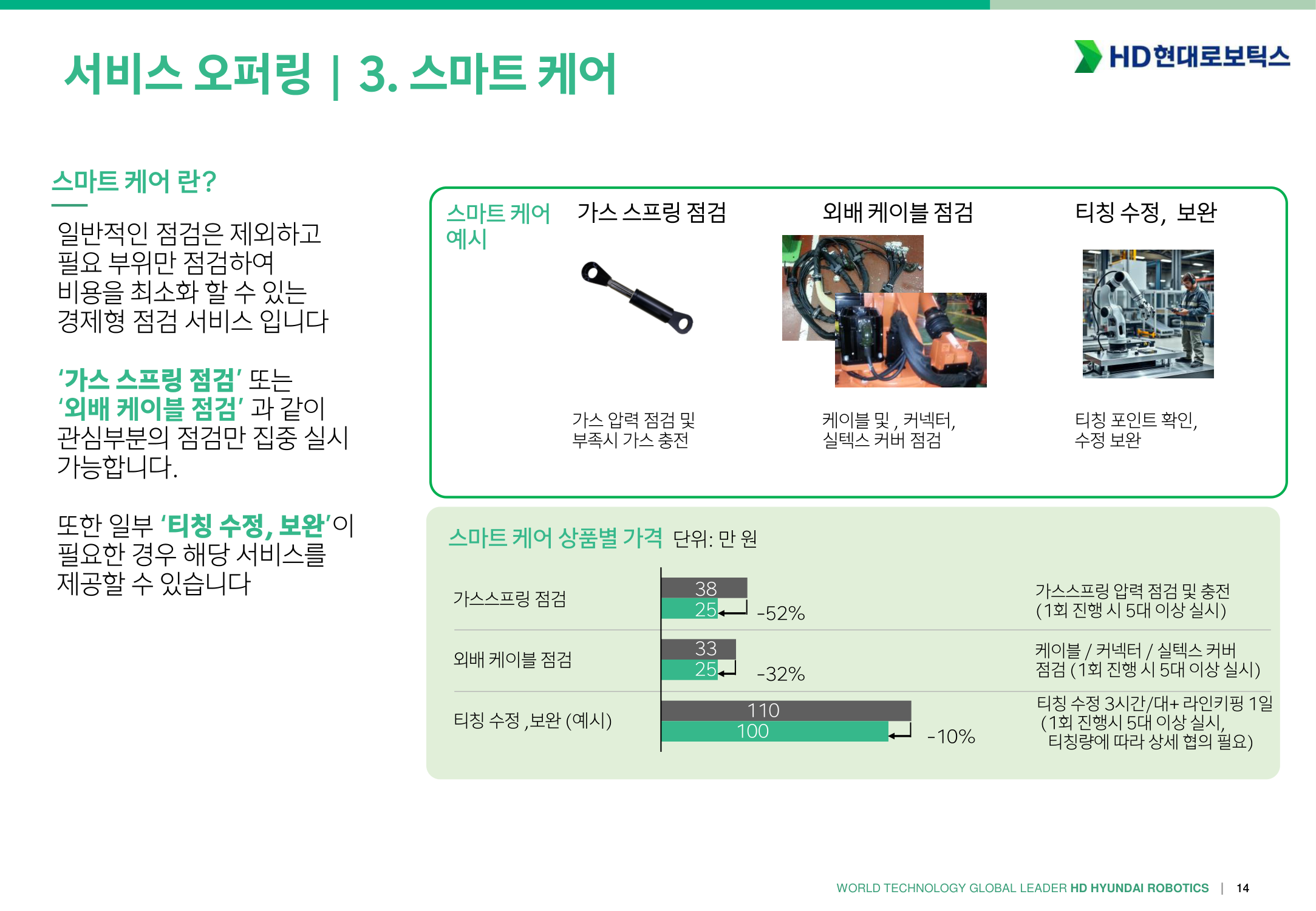
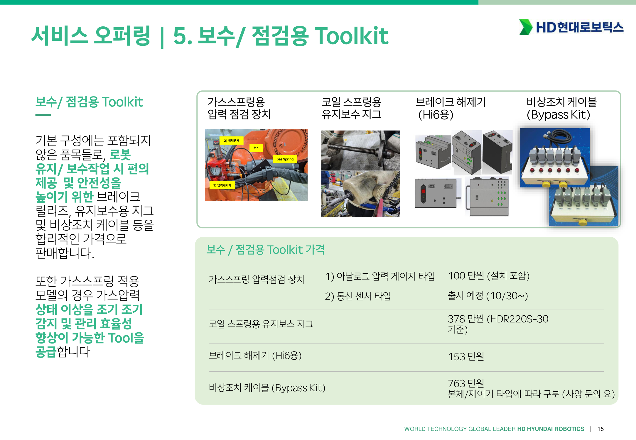
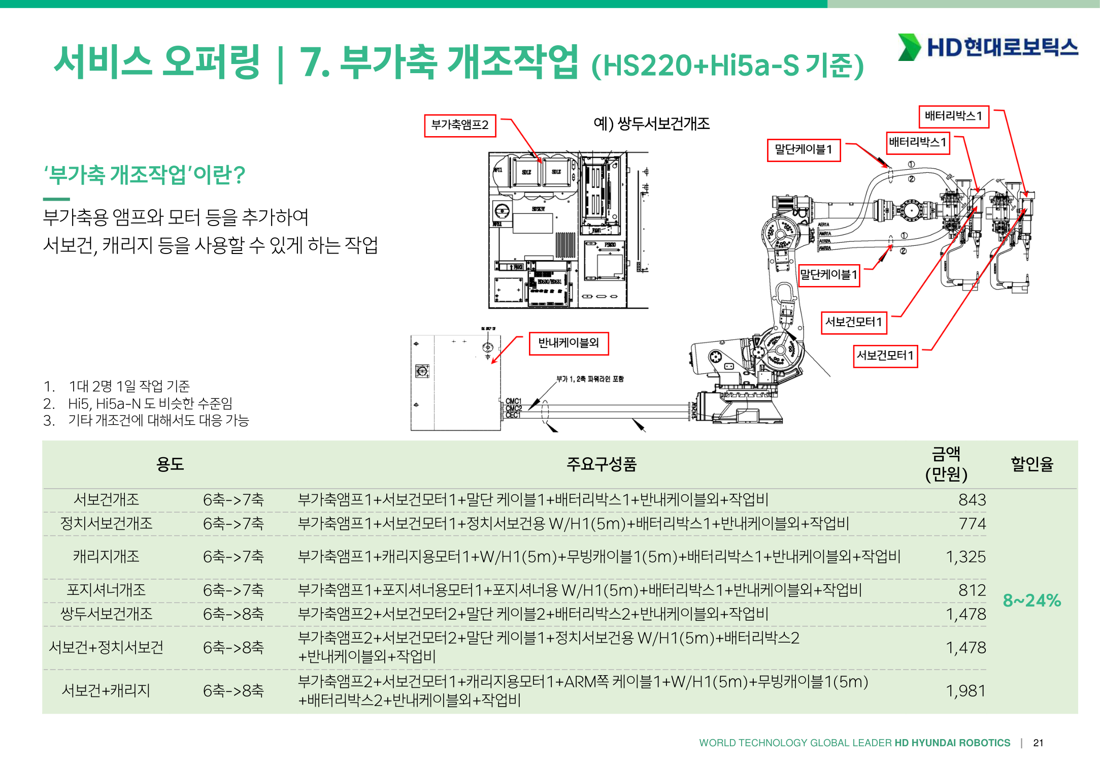
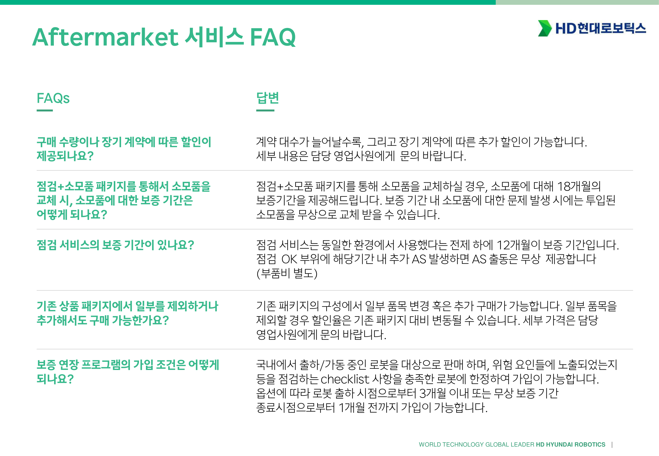
- Aftermarket 서비스 소개
- Hi6 외부IO 결선 작업시 주의사항
- BD525 형번규정
- Hi5a 버전업 방법
- TP520, TP530 SW 구분 사용
- 로봇 가반중량의 이해
- 감속기 그리스 혼유 금지 공지 (VIGO + EUREKA)
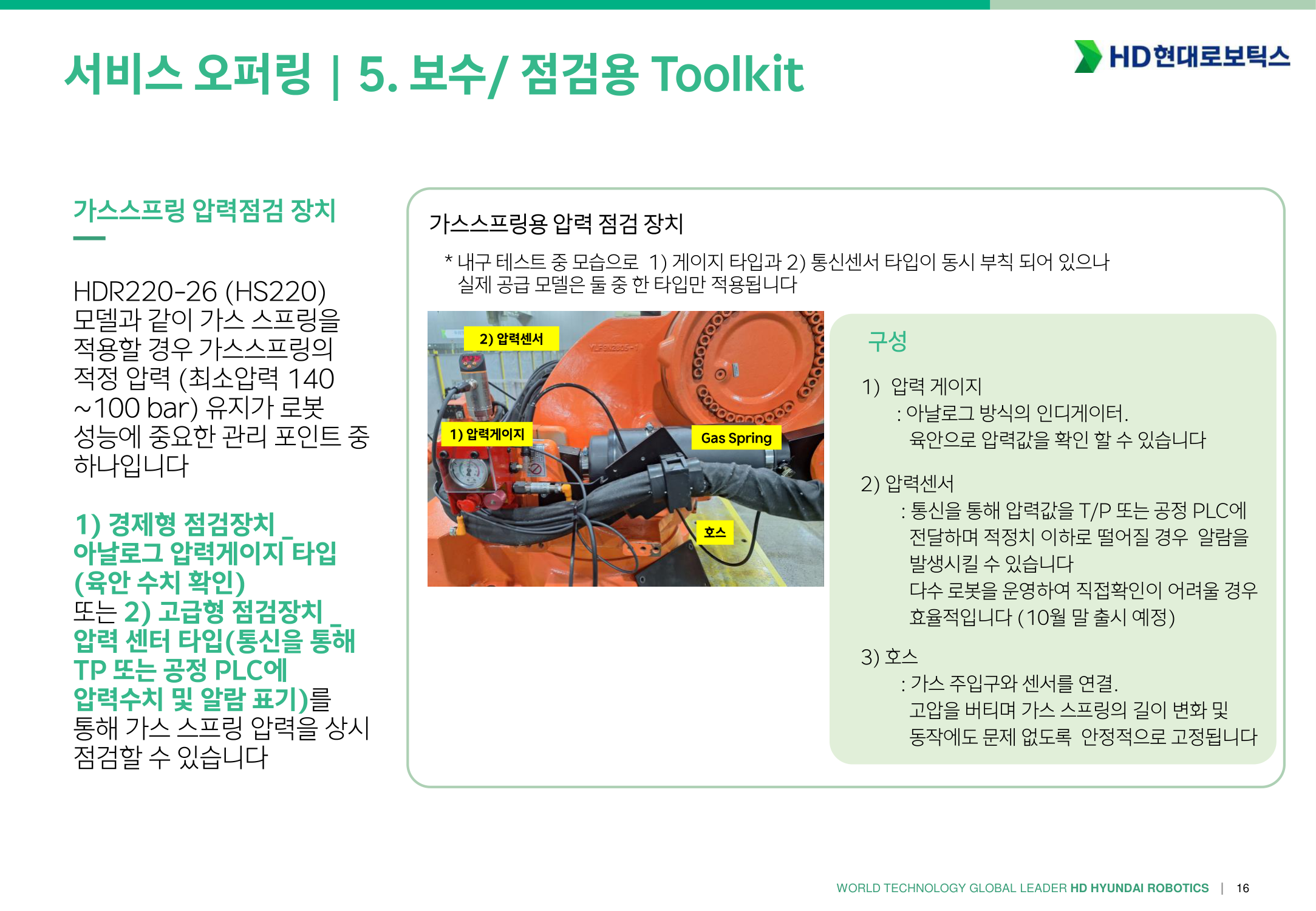
- 가스스프링 관리 - 가스스프링 모니터링 방법
- 가스스프링 관리 - 가스압력 검사와 주입
- 가스스프링 관리 - 점검
- HH7 로봇 원점 확인 방법
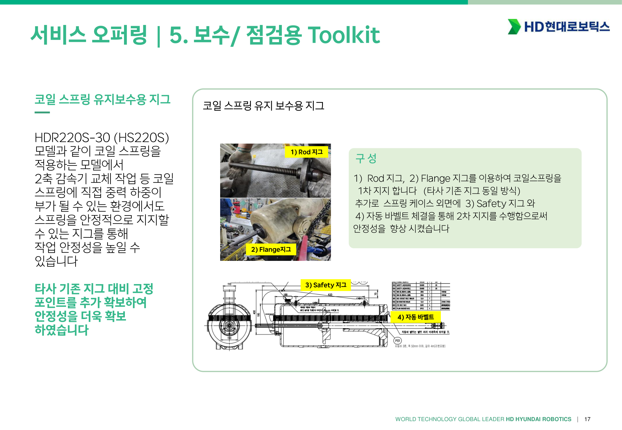
- 가스스프링 관리방법, 점검 교체 주기
목록
· 2 min read
-9c31dcf47f4bd815b42a22843db447fa.png)
-4a996965a251b3ba3fbdfa3941dd4872.png)
-786af3ad17c64c9b1004783d2f28a1e7.png)
-6edf4df748eaf9e6299daa29e2480789.png)